This post will present you with pictures of temporary electrical installations, the temporary switchboards (at this post,
Temporary electrical switchboard), temporary electrical DB, temporary cables and poles.
The post is open ended. I will keep adding more pictures and comments when I find something that I think the readers will be interested in.
Someone also commented that I have yet not uploaded any picture on temporary lighting.
Well, now you have a few of the pictures at this post,
Temporary site floodlights. There is also more information on site lighting here,
Temporary lighting installation.
I have also just sent a new anchor post,
Free electric installation pictures, to partially fulfill a few requests to have all the pics at one place.
So if construction site’s temporary electricity supply is a subject of your interest, keep checking this post every few weeks, you may find new information that you can use.
-----------------------------------------------------------------------------------------------
RELATED POSTS: (a)
Electrical DB installation; (b)
Electrical injury pictures;
.........................................................................................................................
For readers who have visited this site before, you can see that this post keeps changing. That’s because I need to adjust the layout and some contents here and there so the newly added information can fit in and also to make the various content more coherent.
One other thing, if you have the time, check out the following link. It is a link on how to convert your car into an electric car at minimal cost. It is a way we in the electrical industry can contribute in the global effort to
save this planet. In any case, it can save some significant dollars of our daily transport costs. Check it out. It’s a good reading.

Content:
Section A. First case – 20 floors of temporary electricity supply without the
electrical grounding.
Picture 1 – Temporary
switchboard, temporary DB, temporary cables, temporary extension cords, temporary sockets.
Picture 2 – Another temporary DB (Picture quality not so good. Sorry…)
Section B. Another DB – Temporary electrical panel, temporary cables and extension cords.
Picture 3 – Temporary distribution board – Right view
Picture 4 – Temporary distribution board – Front view
Picture 5 – Temporary distribution board – Left view
Section C. Site
temporary electric supply – The risk
Section D. Another case of the electric supply without the earth grounding.
Picture 6 - Electrical panel location (Click on the picture to see full size)
Picture 7- Electrical panel inside view (Click on the picture to see full size)
Picture 8- Earthing copper bar without connection to earth (Click on the picture to see full size)
Picture 9- Incoming 4-core twisted cable without earth (Click on the picture to see full size)
Section E. A simple example of temporary earth
Picture 10 – Temporary electric supply: The complete system
Picture 11 – Temporary cables, temporary meter, temporary distribution board, temporary earth wire and protective PVC conduit.
Picture 12 – Temporary
earth grounding
Section F.
Site power distribution and equipment
The supply equipment
The distribution system
Picture 13 – Temporary electric poles
Picture 14 – Accidents on electric poles
Section G: Is there a foolproof system for a site temporary power?
The weaknesses of RCD (or ELCB)
Diagram 15 – Three- phase reduced low voltage supply system
Diagram 16 – reduced low voltage supply system (single phase)
Section A. First case – 20 floors of temporary electricity supply without the electrical grounding.
Today I am going to share with you a picture of one of the most important parts of
temporary electrical installations in construction works, that is the temporary supply sub-switchboard, distribution board and their cabling.
Below is the picture of a temporary electrical assembly. It was taken at one of my projects a few years ago. What you see in the picture is the floor temporary sub-switchboard, which sits on the left of the assembly. Next to it is the temporary DB with an on-board three phase isolator and a few 13A
switched socket outlets.
Picture 1 –
Temporary switchboard, temporary DB, temporary cables, temporary extension cords, temporary sockets.

The project was a multi-storey residential building and the temporary supply was taken from the temporary
main switchboard at the ground floor. The authority's meter panel was installed at the main switchboard. So the twisted 4-core submain cable was run from the main switchboard to each sub-switchboard at individual floors (one sub-switchboard for every three floors actually). Since it was a 21-storey condominium, seven subswitchboards were installed. From each sub-switchboard, cables were run at high level to distribution boards at various locations at the three floors in its coverage.
Back to the picture… So what is so special about the electrical board assembly in the picture? This is one example of the usual practices in the installation of temporary electrical supply at construction sites in our country. Not all construction sites are like this example, of course. Many job sites practise very good safety standards and I can personally testify to that, but quite frankly the practise shown in the picture is quite common. And in this case I have seen one situation that I have never seen in my entire 18 years of involvement at construction sites. I apologize the picture may not be very clear, but I hope you can see that the incoming cables to the floor sub-switchboard is only four-core. It has NO EARTHING at all.
I joined the supervision team while the work was already quite advanced with only a few month left to the completion. The temporary electrical supply has been in operation for almost a year. The electrical sub-contractor has also been on board for many weeks. Yet the electrical supply distribution from first floor to top floor at Level 21 has no earthing. I was shocked when I notice this on my second day at site. It was unbelievable. Some unlucky workers could have died from this oversight.
The 25 by 3 mm earthing copper tape was finally installed later, after many days of my urging them to do it. The distribution boards and the temporary cabling were also much improved.
As you can see, apart from the earthing conductor, obviously there were a few more things that were wrong with the distribution boards, the cabling and the plug and sockets in the picture. Maybe we can talk again about these in my future posts.
For now I just wish to emphasize the importance of checking the
temporary electrical supply installation at your construction sites. Do not assume that the main contractor of a RM230 million building project will have enough people to look at safety matters as important as this one.
More Temporary Electrical Installations
I have also attached below two more pictures of temporary distribution boards just for the fun of it.
Picture 2 –
Another temporary DB (Picture quality not so good. Sorry…)


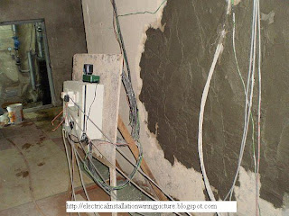
These temporary electrical DB are also located along the main access route inside the building under construction. Exposed, without barricade, without any protection at all. This is
how you can get electric shocks.
That's it for now. When we meet again I will show you a few more pictures of electrical installations from my previous projects and maybe we can learn some things from them.
That's it for now. When we meet again I will show you a few more pictures of electrical installations from my previous projects and maybe we can learn some things from them.
Section B. Another DB – Temporary electrical panel, temporary cables and extension cords.
These pictures I have already posted on my other blog a few months. It’s a new blog I just set up but I don’t have much time to spare on it. So it’s not drawing much traffic. So I thought I might as well put it here so it can be of some use to someone.
Below you will find a few pictures on a temporary electrical panel, sockets, plugs and extension cords. I have added a few comments below the pictures on aspects that I think is important. Further comments will be added when I think of something readers may be interested to know.
Picture 3 –
Temporary distribution board – Right view

Picture 4 – Temporary distribution board – Front view

Picture 5 – Temporary distribution board – Left view
Is there anything wrong with the electrical installation in these pictures? The temporary panel seems to be quite new and definitely in a good condition.
You may question about the mounting method for the panel. But this is a temporary panel for a construction site. At times, the subcontractor needs to move the panel from one place to another every few days. So fixed wall mounted method is not a practical choice this circumstances.
Yes, you may want to suggest that the mounting stand be made of a much better material and design. That I would agree.
The supply temporary cables to the panel seem to be four single core cables. I do not know what size just by looking at the cable from a distance, even though an electrician might be able to give a good guess. Four core means four phases plus one neutral.
You can also see two very good-looking wires with green insulation twisting along the four-cable bunch. These must be the earthing wires, or Circuit Protective Conductor to be precise. Is the total cross section sufficient of the earth wires sufficient? I am a bit rusty on this nowadays. But temporary electrical supply only needs residual current protection as the shock protection. The green wires seem like 4 square mm. Two of them will give 8 sq.mm. I think that should be enough. Of course the required cross section of the earth cables depend on the distance of the temporary panel to the earth electrodes.
That covers the electrical panel and the incoming supply cables. Now let us look at the outgoing circuits from the panel.
First the socket outlets, or the receptacles as the Americans say it. They seem to have the original SIRIM sticker on each of the sockets. In any case all the sockets are new, so there should not be much issue about them. However what has been plugged into each of the sockets is a different matter.
The appliance connected to the right socket of the lower row should be okay. I think it's the charger for a walkie-talkie. All factory-manufactured and all new.
However, the cords connected to the other four sockets may have some serious safety issues. I will add comments on these in the near future.
Have a nice day.
Update Jan. 2010: You can see pictures of 11kV switchboards at my new post
Hospital LV Electrical Installation.
Section C. Site electric supply – The risk
It has always been a challenge to provide the electric supply to the site people safely. Construction sites are among the most challenging environments to the safe use of electricity.
A lot of works are done outdoors, in all sorts of weather conditions. Wet and damp conditions present very high risks of severe
electric shocks.
The workflow of site works is constantly changing as the construction work progresses. Therefore, the temptations to improvise the electrical distribution system are often too great to resist.
Routine construction activities, the demolition and excavation works may all result in damages to both the temporary supply and the newly fixed permanent supply systems.
When the activities at a site are at its peak with hundreds or thousands of workers (not to mention construction vehicles and machineries), the site usually become very congested. This sort of situations makes the control of risks very difficult. Temporary cables and electric construction tools and equipment are very likely to be damaged by the movement of heavy machines and materials.
The people who use electricity at site have various needs, and sometimes conflicting interests and expectations. The workers and team leaders themselves work for different subcontractors and suppliers. In order to maintain any reasonable degree of safety and control of risks, a effective site management is an absolute must-have for the site main contractor or the client’s people who are in charge at the construction site.
Due to the nature of construction works, a risk-free environment is impossible to attain most of the time. However, some risks can be avoided by careful planning before the work commences at the site.
-------------------------------------------------------------------------------------------------
Section D. Another case of the electric supply without the earth grounding.
This is another case of missing electrical grounding that I already published in my other blog.
The following pictures of a temporary electrical panel show another common type electrical hazard at construction sites. I took these photos at a building construction site about four months ago.
This panel was located under a shade at the concrete mixing station of the construction site. As you can see, the location of the electrical panel was full of water. No, it was not due to rainwater. The location was always that way, because the plant consumed a lot of water daily. The situation presented a very high risk of electrocution not just to the worker operating the concrete mixing plant, but also to other workers.
Someone at the site told me that the electrical panel was too high above the water. So there was not really much risk. What do you think?
Picture 6 -
Electrical panel location (Click on the picture to see full size)

I opened the electrical panel door to check inside (See Picture 7). The panel was a good quality and relatively new. The internal wiring inside the panel was also done nicely and it was neat.
But wait.... Where is the earthing to the panel? There was good earth wiring inside the panel - the green wires. All neatly run and properly terminated to the copper earth bar. However, the connection just stopped there. There was no outgoing connection to earth (See Picture 8).
Picture 7-
Electrical panel inside view (Click on the picture to see full size)

Picture 8-
Earthing copper bar without connection to earth (Click on the picture to see full size)

I checked the incoming twisted cable. It was a four-core. No earth cable anywhere (See Picture 9). I checked around the panel to see if the person who installed it used a different conductor and run it direct to earth somehow. Nope, no other conductor installed.
The conclusion? The electrical panel was not earthed at all. So what happens when there is a considerable leakage current? What protects the worker at the concrete mixer machine there, especially with the wet condition there? Sadly to say... no protection at all.
Feeling exasperated, I checked inside the electrical panel again. Surprise... there was not even an
earth leakage circuit breaker there, or any other type of residual current protective device.
Picture 9-
Incoming 4-core twisted cable without earth (Click on the picture to see full size)

I have to go now. I will add more info to this post in the near future. I know there are questions in the minds of some of the readers relating to the electrical installation shown in these pictures. The electric shock protection issue can be tricky sometimes.
Until next time...
Section E. A simple example of temporary earth
The safety of an electric supply often depends on the existence of an effective earth. It is the responsibility of the person in charge of the construction site to ensure that the earthing of the electric supply system is effective. The site’s electricity supplier (the electric supply authority) has nothing to with this part of the electric supply.
Many electricity supply authorities use protective multiple earthing (PME) system. In this system the electrical system’s neutral and earth are combined. When this system is used, all metalwork including structural metalwork must be bonded together in such a way to make all metal parts electrically continuous.
However in most real life construction sites, this bonding is hard to do and almost impossible to maintain properly throughout the duration of the construction period. So usually, the public utility supplier will not connect the supply until an alternative electrical earth is provided and fully tested. They also insist that evidence of the earthing test results endorsed by a competent electrician is submitted together with the completed application forms for the temporary electricity supply to the site.
Several methods are used to provide the alternative electrical earth. The most commonly used method is to use an independent earth electrode installed at the location near the main intake temporary switchboard (this is usually the location where the temporary meter is installed). This will ensure that the protection fuses will operate and disconnect the site electrical installation from the incoming public supply in the event of a fault. This disconnection is an absolute must in order to minimize the damages to the site’s electrical system due to the fault and also to prevent the fault from spreading upstream to the electric supplier’s distribution network. The latter is the main reason the electricity supplier is worried about this aspect of the temporary installations.
Picture 10 –
Temporary electric supply: The complete system

I will devote one whole post in the future for this subject of earthing. But for now I have a few picture of temporary electrical grounding for your viewing pleasures. I seek an apology from those readers who already have some electrical knowledge. These pictures are not for you guys. They are too simple. However for those managers and construction people who have always been intimidated by those colleagues on these sorts of issues, let me assure you that if you understand what these three lousy pictures say, then you already understand what an electrical grounding is.
Picture 11 –
Temporary cables, temporary meter, temporary distribution board, temporary earth wire and protective PVC conduit.

Picture 12 –
Temporary earth grounding

Now lets start with picture 10 (You may need to click on the picture to see it in full size). The black case on the wooden panel there the temporary electric meter supplied by the electric authority. Below it in white PVC casing is the temporary distribution board. You can also see coming out downward from the distribution board a piece of wire in green insulation and this wire goes straight into a two meter length white PVC conduit, and (if you watch it closely) it comes out of the vertical PVC conduit at the bottom and goes straight into the concrete floor just beside the plywood partition wall. All these you can see much more clearly in Pictures 11 and 12.
Back to the black energy meter. Above it you can see two lengths of black insulated cables coming down from high level (below the roof level of the temporary wooden structure). One cable terminates at a black piece of component just above the meter, while the other one terminates at a cheap white plastic terminal block. The two components each have a cable of the same size coming out at the bottom connection and terminate at the temporary kilo-watt-hour meter.
Now lets get a little bit more technical. This is what we call a single-phase electrical installation (a three-phase supply would have four black cables coming down from the roof level – three phase cables and one neutral cable). So the incoming supply from the authority is also a single phase supply (we apply single-phase supply, so they give us a single phase supply).
An electric supply from the authority can be one of a few types. The type as recorded in the pictures is the single-phase two-wire type (three-phase 4-wire if we apply three-phase supply). This type will have two incoming cables from the authority’s distribution network – one live or phase cable and one neutral cable. Other types may have three incoming cables from the distribution network for the same one-phase supply – the same live and neutral cables, plus a third cable, which is the earthing cable.
Now as I said earlier in this post, a construction site really needs an independent and reliable earthing, an electrical grounding that is not dependent on any third party’s grounding or even the electricity supplier’s grounding. Failure to provide this can result in fatal injuries from electric shocks, even multiple casualties in a single accident. Never mind my emotions on this (if you can sense them), but an electrical accident is that dangerous and electrical shocks can strike silently without warning.
Because of the need for that independent and reliable earth for the temporary site supply, the green electric cable is installed below the white PVC distribution board (Picture 11 shows this clearly). Without this cable, the electrical system can still work. The workers can still use their tools and do a good job for their employers so the construction venture can end up being very profitable for the shareholders of the company. But one fine day, an extension cord that carries current to the electric drill one of the workers has been using gets injured, exposing the live wire to an unintentional contact with any of the workers around the area. Being hard at work, the workers bodies and clothes are usually very damp or very wet with sweat. One accidental contact at any part of a workers body with the exposed live conductor of the damaged extension cord, then you will severe electric shock injury, even death is highly likely depending on where on the worker’s body the contact to the live wire happens. If the contact is at the hands, then the electric shock current will travel through the chest and the workers heart before going down to the legs and the ground. Then you may have a case of fatal injuries there.
Sorry for the diversion. This electrical earthing matter is so simple that I have to drag the stories into the injury aspects to make it a bit longer ;-)).
Not only it is simple, it is also plain cheap and low cost. Look at the picture again. You have a short length of the green wire and two meters of the white PVC pipe. Wait… I know what a few of you are thinking… Yes, there is copper earth electrode in the concrete, which goes straight down below the concrete about 1.5 to three meters into the ground.
The example that I use here is a very small installation, so it looks simple. This wooden structure only uses a few amperes. However even for a large installation, the grounding is relatively just as simple.
The point that I am trying to make in this section is that providing an independent and effective earth is not a challenge at all in most situations. So, do not risk human lives just to save some construction cost there.
Section F. Site power distribution and equipment
The supply equipment
Equipment selected for use in a site temporary electric supply distribution need to be designed for use in the environment it in is going to be operated in. During the selection process, the most important is to make sure that the manufacturer’s restrictions of use are considered. For example a sub-switchboard that need to be moved frequently, left exposed under sun, and rain during operation must necessarily be of adequate IP rating.
The construction of the equipment must also be robust enough to withstand the damage caused by the rough treatment at the construction site.
Most of the time, equipment purchased for use at a project site will be transported for use in another project or work locations. Therefore, it needs to have provisions for frequent loading and unloading, transport and storage while throughout all these it cannot be damaged to the point of becoming malfunction and unsafe for use. Under the pressure of worksite demands, even a good site electrician tends to improvise on the safety aspects site electricity supply. With damaged equipment, the risks are compounded even more.
The equipment selected also shall include the provision for isolation of supply and facilities for locking the switches. This is especially important main switchboards and sub-switchboards where the locations of the board and the local distribution boards are quite far away and not within the line of sight.
The distribution system
The distribution system is the system of cabling and equipment that are arranged to distribute the electric power to the various machines and current using locations throughout the construction site. This temporary distribution system will be removed after the construction work is completed and the permanent power supply system is commissioned and operational.
The location of the switchgear and metering apparatus must be secured in terms of security from unauthorized access and safety from damage and the effects of the environmental factors. Access to the switchgears and the main isolation switch must be accessible at all times in case of emergency.
Just because the supply system is temporary does not mean it can be assembled without all the proper engineering calculations and considerations required of a permanent system. Fuses, circuit breakers and cables all must properly selected and sized.
Many practices shown in the pictures of temporary installations above are bad practices. If contractors are allowed to provide these bad installations on site power supply, accidents whether in the form of damaged equipment, fires or electric shock or even electrocutions is bound to happen sooner or latter. Makeshift arrangements such as unprotected wiring, twisted or taped cable joints are often dangerous and cannot be accepted. All the temporary installations works must be done in accordance to the appropriate standards.
Site distribution cables must be properly located. They should not be installed where they are likely to be damaged by the construction activities or vehicles. Picture 13 below shows an example of a site distribution cabling running on temporary electric poles. This method of installation is fine but here they are run across one of the main road within the construction site. The next picture (Picture 14) shows the temporary cables on the ground. Only a few minutes earlier, an earth moving tipper truck accidentally hit and dragged the overhead cable while unloading the earth for a drainage work next to the temporary poles. There were workers nearby when it happen, including me. Luckily, no one was injured.
The above accident could have been prevented if the stretch of the cables crossing the construction have buried in a G.I. pipe just two or three feet below the road. With all the construction machineries at the site, these could have been done in a matter of one or two hours. However, here the main contractor chose the easy way and just installed the whole stretch on poles.
Picture 13 –
Temporary electric poles

Picture 14 –
Accidents on electric poles
 Section G: Is there a foolproof system of site temporary electricity?
RCD (or ELCB)
Section G: Is there a foolproof system of site temporary electricity?
RCD (or ELCB)
RCD (residual current devices) or
ELCB (earth leakage circuit breaker) is not an ideal device for use in the tough environment of construction sites. It may not even be possible to maintain the integrity of the housing where the RCD devises are housed in.
It is also not the kind of devices that can be fitted on portable equipment, which usually are subject to mechanical shocks and vibration.
Electric shock protection based on RCD alone has many weaknesses. It cannot guarantee safety.
a) When an RCD malfunctions or it fails to operate, this failure can go unnoticed so the affected workers are unaware of the dangers awaiting to turn into accidents.
b) The RCD only protect against faults to earth, and it required sufficient bonding to earth for operation. It cannot operate when there is no earth connection, for example, when current passing from live to neutral. This type of situation is still dangerous: the workers can still get electric shock, injuries or even electrocution even though the RCD is working properly.
c) The use of RCD will not make the system safe if it is not properly designed, properly installed and adequately maintained. The popularity of RCD may have been due to difficulties to obtain low earth resistance on many installation conditions. However, RCD is not a substitute for reliable and efficient earth grounding.
d) RCD designed for electric shock protection have a rated tripping current of 30 mA. At sites where temporary load requirements are higher, installing a 30 mA at the point of intake (like an ELCB installation in a house distribution board) will lead to frequent unnecessary tripping, shutting off the supply to the whole site.
e) Electrical loads at construction sites consist of tools and equipment that have high leakage currents. This factor has led to many ‘nuisance’ tripping of the supply. These are also unwanted tripping that frequently lead to the RCD devise being defeated in some by the workers involved, leaving the whole supply system with a shock protection.
f) RCD can be chosen to be very sensitive to small current leakage, and trip fast enough to avoid serious injuries. However, with this principle, it only limits the duration of time that the current flows in the event of shock, it does not limit the magnitude of the current flowing. If the devise fails to operate, the current will continue to flow continuously. Even low shock current if allowed to flow continuously through the body can cause serious injuries.
Reduced Low Voltage supply
Most of the time the electric shocks that occur are between the live parts and earth, which are the results of damaged cable insulations, faulty power plugs, or faulty or damaged equipment. Whatever is done to the electrical system, or the electric shock protection to reduce the risk of shock to people, the potential is always there. RCD itself is a active electromechanical system that can fail. It effectiveness requires an effective earth which can be hard to maintain in a real life construction sites. While the scope of protection covered by the device still have gaps, that is left without shock protection (between live and neutral).
Fortunately, there is one system that has been proven almost foolproof against electric shocks at construction sites. It is called the reduced low voltage system, where the supply voltage is stepped down to a level which is practically safe without depending too much on an active shock protection, or a sophisticated system that is hard to implement at construction sites.
This system reduced the 415/ 240 volts supply voltage to 110/64 volts for a 3-phase supply. If only 1-phase supply is needed, then a 240/ 110 volt center-tapped transformer is used to reduce the single phase voltage to 110 volts with the electrical grounding connected to the center of the secondary transformer coil. This will present a maximum possible risk of only 55 volts to the users of the electricity instead of 240 volt (or 415 volts for 3-phase) as I the original 415/240 volts supply.
Technical studies that have been carried out have shown that the maximum indirect contact touch voltage to earth is only 40 volts. This is below the danger voltage as specified by the IEE Regulation. Even the SELV (safety extra low voltage system) as specified in the regulation is 50 volts.
The following diagrams show the basic configuration of the reduced low voltage supply system.
Diagram 15 –
3-phase reduced low voltage supply system

Diagram 16 –
single-phase reduced low voltage supply system

(c) copyright http://electricalinstallationblog.blogspot.com
Temporary Electrical Installations


